Update to PSU Testing 2015: A Minor Change
by E. Fylladitakis on May 4, 2015 11:00 AM EST- Posted in
- PSUs
- Cases/Cooling/PSUs
- Testing Procedures
Today I want to discuss a minor change in our PSU testing procedures, and how they have evolved since our 2014 - How We Test PSUs pipeline post.
To date, all of our testing was being done in accordance with Intel's Power Supply Design Guide for Desktop Form Factors and with the Generalized Test Protocol for Calculating the Energy Efficiency of Internal AC-DC and DC-DC Power Supplies. These two documents describe in detail how the equipment should be interconnected, how loading should be performed (as the power lines should not just be loaded randomly), and the basic methodology for the acquisition of each data set.
However, not all of our testing can be covered and/or endorsed by these guidelines.
Even though these documents are just a few years old, their methods fail to account for modern "enthusiast grade" computer switching mode power supplies. The industry has been making leaps on the creation of more energy-efficient devices, continuously lowering their power requirements. Nowadays, the vast majority of computers that require very powerful PSUs simply employ multiple components, such as numerous graphics cards. As the majority of energy-consuming components require a 12 V source, PSU manufacturers have been continuously driving the 12 V output of their units upwards, while the 3.3V/5V outputs remained inert or are getting weaker. There are many design rules that modern "enthusiast-grade" PSUs do not adhere to nowadays, such as the current safely limits and the maximum size of the chassis, but this particular change creates a problem with the generalized test protocol.
Furthermore, nearly all switch mode power supplies with multiple voltage rails will exceed their maximum rated power output if all the rails are loaded to their maximum rated current. This includes nearly every PSU ever made for a PC. It is not possible to load every rail (3.3V, 5V, 12V, 5VSB, -12V) to its maximum rated current without severely overloading the PSU. For this purpose, the derating factor D exists, which calculates the contribution of each rail in relation to the maximum output of the PSU. The derating factor for a computer PSU always has a value lower than one. A lower derating factor indicates overly powerful lines in relation to the total output of the PSU, which practically is good. A value greater than one would suggest that fully loading every rail does not exceed the maximum power output of the PSU, which is never the case with a PC power supply.
According to the generalized test protocol, the derating factor D of the 3.3V/5V lines should be:
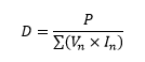
Simply put, the formula is maximum rated power output of the unit divided by the sum of the power output ratings of each individual power line.
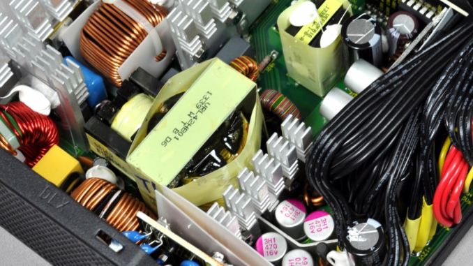
However, this formula frequently leads to the overloading of the 3.3V/5V lines with >1 kW PSUs. The effect is particularly severe in some high efficiency units, in which the designers moved the 3.3V/5V DC-to-DC conversion circuits on the connectors PCB, reducing their maximum power output significantly. Although some PSUs would operate normally even if their 3.3V/5V lines were overloaded, the continuous degradation of the 3.3V/5V lines in comparison to the 12 V line resulted to PSUs appearing in our labs that could not operate under such conditions.
The grandest example of them all would be the Andyson Platinum R 1200W PSU that we reviewed just recently. This PSU has a lopsided design such that the 3.3V/5V rails that can output just 100W combined, which is nothing compared to the 1200W the single 12V rail can output. Furthermore, the current rating of the 5V line alone can reach the maximum output reserved for both the 3.3V and 5V rails. This great imbalance creates an issue with the generalized PSU testing protocol, which has been developed for PSUs that do adhere to the design guide standards. If we were to load that PSU using the standard derating factor formula, it would create a load of over 150 Watts on the 3.3V and 5V rails, which were rated for an output of just 100 Watts. Other units did work with their 3.3V and 5V rails slightly overloaded but, in this case, the Platinum rated unit failed long before it reached its maximum output. Therefore, it was obvious that the official derating factor calculation method could no longer be used for modern high output PC PSUs.
Therefore, we had to alter the derating factor formula in order to compensate for real world testing. Without at least two significant energy consumers, no modern system requires > 500 Watts. Greater power demand suggests the presence of devices that load only the 12 V line (i.e. GPUs, CPUs, liquid cooling pumps, Peltier effect coolers, etc.). After certain calculations and research, for units with a rated power output over 400 Watts, we will be using the following formula:
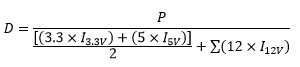
Which effectively halves the impact of the 3.3V/5V lines on the calculation of the derating factor, imposing the difference on the 12V line. This does not mean that their load is being halved, only that their contribution to the total output of the PSU is now considered to be of lower importance. Furthermore, the loading criterion of the 3.3V/5V lines for a load rating X (in % of the unit's maximum output) is now changed to:
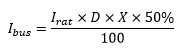
For the 12 V line(s), the loading criterion remains unchanged.
This formula results to the more realistic representation of the requirements that actual systems have, at least up to a power output realizable today.
Furthermore, there are no guidelines on how transient tests should be performed and the momentary power-up cross load testing that Intel recommends is far too lenient. Intel recommends that the 12 V line should be loaded to < 0.1 A and the 3.3V/5V lines up to just 5 A. We also perform two cross load tests of our own design.
In test CL1, we load the 12 V line up to 80% of its maximum capacity and the 3.3V/5V lines with 2 A each.
In test CL2, we load the 12 V line with 2 A and the 3.3V/5V lines up to 80% of their maximum combined capacity.
The End Result
If that all sounded like jargon, the end takeaway cause is this - due to user requirements of high wattage power supplies, manufacturers have altered the design of their products outside of the specification documents in order to compensate for cost and engineering prowess.
A power supply should have a balance between the 3.3V/5V and the 12V rails, such that when one is increased the other will rise as well. However this doesn't happen with high wattage power supplies like the specifications says it should. Normally the power rating advertised should be based on this balance, but it doesn't have to. It means that some designs are not like others, and the level of balance is different to get to the power rating.
If the OEMs did adhere to specifications, the cost of the end product would increase to accomodate the higher wattage 3.3V/5V outputs, which is bad for a product that sells based on margins. Meanwhile the extra power that users actually need is all on the 12V, after all, so keeping parity with the guidelines is perhaps a fruitless task. But this means the products do not follow the guidelines, much in the same way that some cars disregard emission guidelines in various markets. The end result is that by testing against the guidelines, the results become erroneous because the device isn't built to strict specification.
Nevertheless the design underneath still works for the user, just like the car with high emissions still drives like a car. You just can't test it like a normal car, or some of the guidelines no longer apply. As a result, we're going to adjust our testing on a sliding scale. If we didn't, some units that will work happily in a real system might fail on our test-bed well before we hit 100% load. The culprit is that 'guidelines' are ultimately not 'rules', and these guidelines can be blurred without proper inspection and preparation.


18 Comments
View All Comments
Duncan Macdonald - Monday, May 4, 2015 - link
One thing that should be added to the tests - noisy power consumption. Modern graphics cards have current loadings that vary wildly from millisecond to millisecond but almost all tests are carried out with smooth loads. For a test that more closely reproduces the load in a PC, the load current of a modern graphics card playing a demanding game should be recorded and that same load profile (scaled according to the PSU rating) should be applied to the PSU. The voltage regulation for a static load is likely to be far better than for a load that varies from 10% to 90% then back again many times a second. Varying loads can also put a higher strain on the PSU - a PSU that can provide 700W as a steady load may fail at a highly dynamic load that never exceeds 650W.extide - Monday, May 4, 2015 - link
I agree with this, but unfortunately executing that sort of test is going to be pretty difficult. First of all you are going to need to put a shunt and an oscilloscope on the rails of the video card (much like tom's hardware did on one of their GPU power articles -- they actually intercepted the power coming in through the pcie slot + the power from the extra connectors). Then you are pretty much going to need to build something to 'replay' that power trace. Probably something that has a MCU and a TON of FET's on a heatsink, and the MCU could switch them on and off. As far as I know there aren't really any devices out there that can replay back a power useage recording like that...Hrmm, interesting idea though. Would be a fun little project to build that dynamic load though.
Duncan Macdonald - Monday, May 4, 2015 - link
If you asked Tom's Hardware they might give you the data from their recording - save you from having to do it yourself. The actual dynamic load is basically a (very) heavy duty D/A, seven bit accuracy and a 10kHz sample rate would suffice.(A Raspberry Pi could drive it or if you have an old PC around then the D/A could even be driven from the printer port!!!)
TurboTastic - Tuesday, May 5, 2015 - link
As described in the "How We Test PSUs 2014" article at http://anandtech.com/show/7820/how-we-test-psus-20... , they have several Maynuo M9714 programmable loads. These can do sinusoidal, trapezoidal, or other regular waveforms, change between two states on an external trigger, or be run (slowly) over GPIB with a preprogrammed array of data (product manual: http://www.maynuo.com/downloadfile/201001195766356...For component validation, it's much more common to apply a regular waveform, such as a 100 Hz trapezoidal waveform from 10 to 90%, than to try to replay a recording. That is done in some tests, but (speaking as a controls engineer in the test and measurement industry) the hard part of testing is not applying the test load, it's quantifying the results. Some (relatively) simple math will tell you the amplitude of the error if you have a regular waveform and an oscilloscope trace. It's much more difficult to look at a half hour of data responding to what might as well be random stimuli at 200 MHz and make any sense of what happened. The only time that you'd really want to do that is if you're measuring something a layer removed from the stimulus - heat generated, total power consumed, and so on. "Average" or "Worst" error level wouldn't be very useful.
jann5s - Monday, May 4, 2015 - link
It would be really cool if you could complement this story with a few measurements of power usage per rail of a few of the anandtech testbeds. Just to put this in perspective.ImSpartacus - Monday, May 4, 2015 - link
Can we just have reviews of more modest psus?As a consumer, it doesn't help me to read a review of a gigantic psu. I don't really about anything more than ~600W.
jann5s - Monday, May 4, 2015 - link
+1r3loaded - Monday, May 4, 2015 - link
Heck, even dual-GPU enthusiast machines don't need more than 700W-800W, tops. 1kW+ PSUs are only of interest to those running triple or quad GPUs which is a very tiny minority of a minority.Impulses - Monday, May 4, 2015 - link
Generally they don't, and ultimately we're headed down a more efficient road... Dual R9 290s would put quite a max load on a 700W unit tho... I ended up upgrading the 750W unit I happily used with my 2x 6950 because of that, if only I'd seen the GTX 970 coming. :pDanNeely - Monday, May 4, 2015 - link
I wouldn't be too quick to assume that because nVidia's used it's advantage in the 700/900 series GPUs to run at cooler default settings (quieter and potentially lower failure rates). AMD is currently cutting prices and throwing more power at their chips for a given level of performance to stay competitive. A few generations back when the 4xx series were dogs nVidia did the same; the next time they have the weaker chip I'd expect them to do the same.